FlowPro

CFD software written in JAVA


Mesh format description

The basic mesh format for FlowPro simulation is described by four txt files saved in directort simulation/"simulation name"/mesh.

The first file's name is vertices.txt. In this file, the x,y,z coordinates of mesh vertices are stored.

The second file's name is elements.txt. In this file, the nubers of elements vertices are stored.

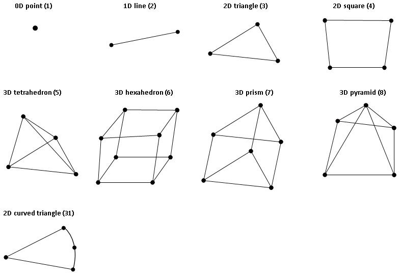
The third file's name is elementType.txt. In this file, the elements type are stored. The all of allowable types are figured bellow.

Fig2. Basic FlowPro element types.

The fourth file's name is boundaryType.txt. In this file, the face boundary conditions are defined. At each of lines, the first number means boundary condition type (negative value) and other numbers are the face point indexes.

Mesh format example

For example let consider the mesh figured at the picture bellow.
vertices.txt
x1 y1
x2 y2
x3 y3
x4 y4
x5 y5
x6 y6
...
elements.txt
2 5 3
5 4 3
7 4 5
7 8 4
9 8 7
...
elementType.txt
3
3
3
3
3
...
boundaryType.txt
-2 1 2
-2 2 3
-1 3 4
-1 8 4
-3 8 9
-3 10 9
-1 1 6
-1 6 11
-1 10 11

Simulation parameters

Computational parameters and model parameters should be defined before simulation running. The parameters are specified in file parameters.txt and must be saved into a simulation directory. FlowPro software include a basic template with parameters need for simulation running. Further each of modules contain a template with mathematical model parameters. For creation a parameter file simple run FlowPro manager using a command: java -jar FlowProManager createparamfile. Then follow the instruction and file with parameters will be created.